


Characteristic
Characteristic
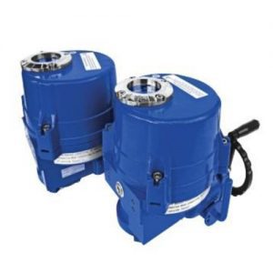
- Bi-directional AC motor
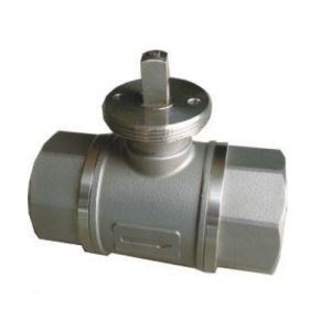
- Apply to valves of DN32 to DN50 (can be also apply to valves of DN15-25 as per request)
- Fire-retardant ABS engineering plastic, measure up UL94V-0 standard
- With manual switch and position indicator
- Floating type or modulating type (within ternal PCB)
- Detachable design, easy to install and maintain
- Fluid temperature and ambient temperature are hard to reach inside of actuator.
- High reliable and safety requirement level
- Actuator manual handle can be disassembled to install on the valve stem for opening or close the valve.
- 0(2)~10V dc or 0(4)~20mA dc control input signal, proportional control.
- 0~10V feedback signal.
- With LED open degree display for option
Model Selection

Specification

Wiring

Installation Instruction

Manual Switch

Actuator Installation

PCB Setting
PCB Setting
- Calibration mode: After power is on, set JP1 switch “4” to position “ON” as request (refer to the below diagram), then press SW1 calibration/reset button, power LED is flashing during calibration, and the actuator stem is rotating till to the end (has reached the end position of ball valves). After ward the stem will rotate back to initial position. Power LED will stop flashing after the calibration mode is over. MCU will keep the position data in memory even power is off. Then JP1 switch “4” is needed to set to “OFF” after calibration is finished and back to operation mode. If this JP1 switch ”4” is forgotten to set to “OFF” during operation, the actuator will operate as usual, but it will go through the calibration mode every time when power is on.
- Operation mode: When power is on, the actuator will work according to the control signal.
- Calibration/operation mode shift: If user needs to switch calibration/operation mode, make sure the JP1 has been set correctly, then press SW1 calibration/reset button. Don’t need to cut off power.